
ESP32 Home Automation — 4-Channel Relay, RGB LED & Android App over WiFi

Imagine walking into a room and controlling every light, fan, and appliance from your phone — no voice assistant, no subscription, no cloud. Just your ESP32 on the same WiFi network as your Android phone, responding to your commands in milliseconds.
In this tutorial you will build a complete home automation system from scratch. The ESP32 connects to your home WiFi, runs a lightweight HTTP server, and controls four mains-voltage devices through an optocoupler relay module. An RGB LED gives you live visual status. A simple Android app (built in MIT App Inventor — no coding needed) sends on/off commands over your local network.
This project is safe, practical, and fully offline — no data leaves your home network.
What You Need
WiFi.h and WebServer.h — both are included with the ESP32 board package. Go to Boards Manager, search esp32 by Espressif and install it if you haven't already.
How It Works
The system uses a simple client-server model entirely on your local WiFi network. No internet, no cloud, no third-party service required.
-
ESP32 boots and connects to WiFi
It joins your home network and gets a local IP address (e.g.
192.168.1.105). The RGB LED turns orange while connecting and green once connected. -
HTTP server starts on port 80
The ESP32 listens for incoming HTTP GET requests on routes like
/relay/1/onand/relay/1/off. -
Android app sends commands
When you tap a button in the app, it sends a GET request to the ESP32's IP address. The ESP32 responds with a JSON confirmation.
-
Relay switches the appliance
The optocoupler relay module electrically isolates the low-voltage control side from the mains side, keeping your ESP32 safe. LOW signal = relay ON (active-low module).
-
RGB LED reflects overall status
Orange = connecting, Green = idle/connected, Blue = at least one relay active. You can see the system state at a glance.
Wiring Diagram
Connect all components as shown below. The relay module requires 5V — use the VIN pin on the ESP32 (which passes USB 5V through). The RGB LED and all control signals run at 3.3V from the ESP32 GPIOs.
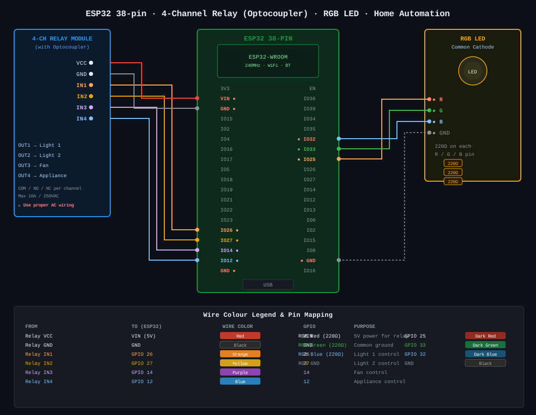
4-Channel Relay → ESP32
RGB LED → ESP32
ESP32 Code
Upload this sketch via Arduino IDE. Set your board to ESP32 Dev Module, select your COM port, and replace YOUR_WIFI_SSID and YOUR_WIFI_PASSWORD with your router credentials.
#include <WiFi.h>
#include <WebServer.h>

// ── WiFi credentials ─────────────────────────────────────
const char* ssid     = "YOUR_WIFI_SSID";
const char* password = "YOUR_WIFI_PASSWORD";

// ── Relay pins (active-LOW with optocoupler module) ───────
#define RELAY1_PIN 26   // Light 1
#define RELAY2_PIN 27   // Light 2
#define RELAY3_PIN 14   // Fan
#define RELAY4_PIN 12   // Appliance

// ── RGB LED pins ──────────────────────────────────────────
#define RED_PIN   25
#define GREEN_PIN 33
#define BLUE_PIN  32

WebServer server(80);

bool relay1 = false;
bool relay2 = false;
bool relay3 = false;
bool relay4 = false;

// ── RGB helpers ───────────────────────────────────────────
void setRGB(bool r, bool g, bool b) {
  digitalWrite(RED_PIN,   r ? HIGH : LOW);
  digitalWrite(GREEN_PIN, g ? HIGH : LOW);
  digitalWrite(BLUE_PIN,  b ? HIGH : LOW);
}

void updateStatusLED() {
  bool anyOn = relay1 || relay2 || relay3 || relay4;
  if (anyOn) setRGB(false, false, true);   // Blue  = relay(s) active
  else       setRGB(false, true,  false);  // Green = idle, connected
}

// ── Relay control helper ──────────────────────────────────
void setRelay(int num, bool state) {
  int pin;
  switch (num) {
    case 1: pin = RELAY1_PIN; relay1 = state; break;
    case 2: pin = RELAY2_PIN; relay2 = state; break;
    case 3: pin = RELAY3_PIN; relay3 = state; break;
    case 4: pin = RELAY4_PIN; relay4 = state; break;
    default: server.send(400, "application/json", "{\"error\":\"Invalid relay\"}"); return;
  }
  digitalWrite(pin, state ? LOW : HIGH);  // active-LOW module
  updateStatusLED();
  server.send(200, "application/json",
    "{\"relay\":" + String(num) + ",\"state\":\"" + (state ? "on" : "off") + "\"}");
}

// ── HTTP route handlers ───────────────────────────────────
void handleStatus() {
  String json = "{\"relay1\":" + String(relay1 ? "true" : "false") +
                ",\"relay2\":" + String(relay2 ? "true" : "false") +
                ",\"relay3\":" + String(relay3 ? "true" : "false") +
                ",\"relay4\":" + String(relay4 ? "true" : "false") + "}";
  server.send(200, "application/json", json);
}

void setup() {
  Serial.begin(115200);

  // Relay pins — all OFF at boot (HIGH = off for active-low)
  int relayPins[] = { RELAY1_PIN, RELAY2_PIN, RELAY3_PIN, RELAY4_PIN };
  for (int i = 0; i < 4; i++) {
    pinMode(relayPins[i], OUTPUT);
    digitalWrite(relayPins[i], HIGH);
  }

  // RGB LED
  pinMode(RED_PIN,   OUTPUT);
  pinMode(GREEN_PIN, OUTPUT);
  pinMode(BLUE_PIN,  OUTPUT);
  setRGB(true, false, false);  // Red = not yet connected

  // Connect to WiFi
  WiFi.begin(ssid, password);
  Serial.print("Connecting to WiFi");
  while (WiFi.status() != WL_CONNECTED) {
    delay(500);
    Serial.print(".");
    // Blink orange while connecting
    setRGB(true, false, false);
    delay(200);
    setRGB(false, false, false);
  }

  Serial.println("\nConnected!");
  Serial.print("IP Address: ");
  Serial.println(WiFi.localIP());
  setRGB(false, true, false);  // Green = connected, idle

  // Register HTTP routes
  server.on("/relay/1/on",  []() { setRelay(1, true); });
  server.on("/relay/1/off", []() { setRelay(1, false); });
  server.on("/relay/2/on",  []() { setRelay(2, true); });
  server.on("/relay/2/off", []() { setRelay(2, false); });
  server.on("/relay/3/on",  []() { setRelay(3, true); });
  server.on("/relay/3/off", []() { setRelay(3, false); });
  server.on("/relay/4/on",  []() { setRelay(4, true); });
  server.on("/relay/4/off", []() { setRelay(4, false); });
  server.on("/status",      handleStatus);

  server.begin();
  Serial.println("HTTP server started");
  Serial.println("Control URL: http://" + WiFi.localIP().toString());
}

void loop() {
  server.handleClient();
}
192.168.1.105). You will need this for the Android app. You can also check it in your router's connected devices list.
Android App
The Android app is built using MIT App Inventor — a free visual drag-and-drop builder. No Java or Kotlin needed. You create the UI by placing buttons and set up the logic with blocks, similar to Scratch.
App Inventor setup
-
Open MIT App Inventor
Go to appinventor.mit.edu and sign in with a Google account.
-
Create a new project
Start a new project and name it HomeAutomation.
-
Add buttons in Designer view
In the Designer view, add a
Labelfor the title and 8 Buttons — one ON and one OFF for each relay. -
Label each button
Name them: Light 1 ON / Light 1 OFF / Light 2 ON / Light 2 OFF / Fan ON / Fan OFF / App4 ON / App4 OFF.
-
Add the Web component
From the Connectivity palette, drag a Web component onto the screen. It appears below the viewer as a non-visible component.
App Inventor blocks
Switch to the Blocks view and wire up each button. For each button, the pattern is identical — only the URL changes:
// Replace 192.168.1.105 with your ESP32's actual IP address
// ─────────────────────────────────────────────────────────

// When Light1_ON button is clicked:
Web1.Url = "http://192.168.1.105/relay/1/on"
Web1.Get()

// When Light1_OFF button is clicked:
Web1.Url = "http://192.168.1.105/relay/1/off"
Web1.Get()

// When Light2_ON button is clicked:
Web1.Url = "http://192.168.1.105/relay/2/on"
Web1.Get()

// When Fan_ON button is clicked:
Web1.Url = "http://192.168.1.105/relay/3/on"
Web1.Get()

// When Appliance_ON button is clicked:
Web1.Url = "http://192.168.1.105/relay/4/on"
Web1.Get()

// Repeat the same OFF pattern for each button
// ─────────────────────────────────────────────────────────
// To check status — GET http://192.168.1.105/status
// Response: {"relay1":false,"relay2":true,"relay3":false,"relay4":false}
Build & install the APK
When the app is working correctly, go to Build → Android App (.apk). App Inventor will generate a download link. Transfer the APK to your phone and install it. Make sure Install from unknown sources is enabled in your phone settings.
Testing Your Build
-
Upload and open Serial Monitor
Upload the sketch and open Serial Monitor at 115200 baud. Wait for the IP address to appear and the RGB LED to turn green.
-
Test relay via browser
From any browser on the same WiFi, open
http://<ESP32-IP>/relay/1/on. The first relay should click ON and the LED turns blue. -
Check the status endpoint
Open
http://<ESP32-IP>/statusand confirm the JSON response shows"relay1": true. -
Test via the Android app
Open the Android app and tap Light 1 ON — the relay should click and the LED stay blue. Tap Light 1 OFF — relay clicks off, LED returns green.
-
Test all four relays at low voltage
Run each relay one by one before connecting any mains wiring. Use an LED with a resistor or a 5V USB bulb to confirm switching safely.
Next Steps
- Add a web dashboard — The ESP32 can serve an HTML page with toggle buttons directly from its HTTP server. No app needed — works on any browser on your network.
- Timer schedules — Use the
time.hlibrary with NTP to automatically switch relays on/off at set times (e.g. turn off lights at midnight). - MQTT protocol — Replace the HTTP server with MQTT (using the PubSubClient library) for faster, more reliable messaging and integration with Home Assistant.
- Voice control — Connect to Google Assistant or Alexa via IFTTT webhooks — they can call your ESP32's HTTP endpoints.
- More relays — Chain a second 4-channel relay module to control 8 devices total. ESP32 has plenty of GPIO pins remaining.
- Current sensing — Add a PZEM-004T module to the relay output to monitor actual power consumption per channel.